
This guide assumes that you have already read through and followed the steps of the 'Opening the ERS-1000 body shells' and ERS-1000 Back Sensor disassembly' guides. If you haven't already read through those guides, do so first as the steps in those two guides have to be carried out BEFORE following this guide.
This page gives step by step guidance on how to disconnect, remove and disassemble the ERS-1000's tail module.Please do so at your own risk.
このガイドは、「ERS-1000 本体シェルの開封」および「ERS-1000 バックセンサーの分解」ガイドをすでにお読みになり、その手順を実行していることを前提としています。まだこれらのガイドをお読みでない場合は、このガイドに従う前に、これらの 2 つのガイドの手順を実行する必要がありますので、まずお読みください。
このページでは、ERS-1000 のテールモジュールの接続を解除、取り外し、分解する方法について、手順を追って説明します。作業は自己責任で行ってください。
このページでは、ERS-1000 のテールモジュールの接続を解除、取り外し、分解する方法について、手順を追って説明します。作業は自己責任で行ってください。
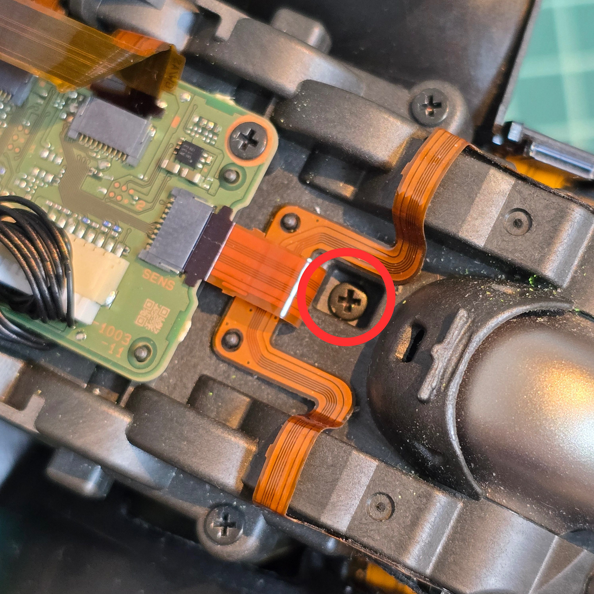
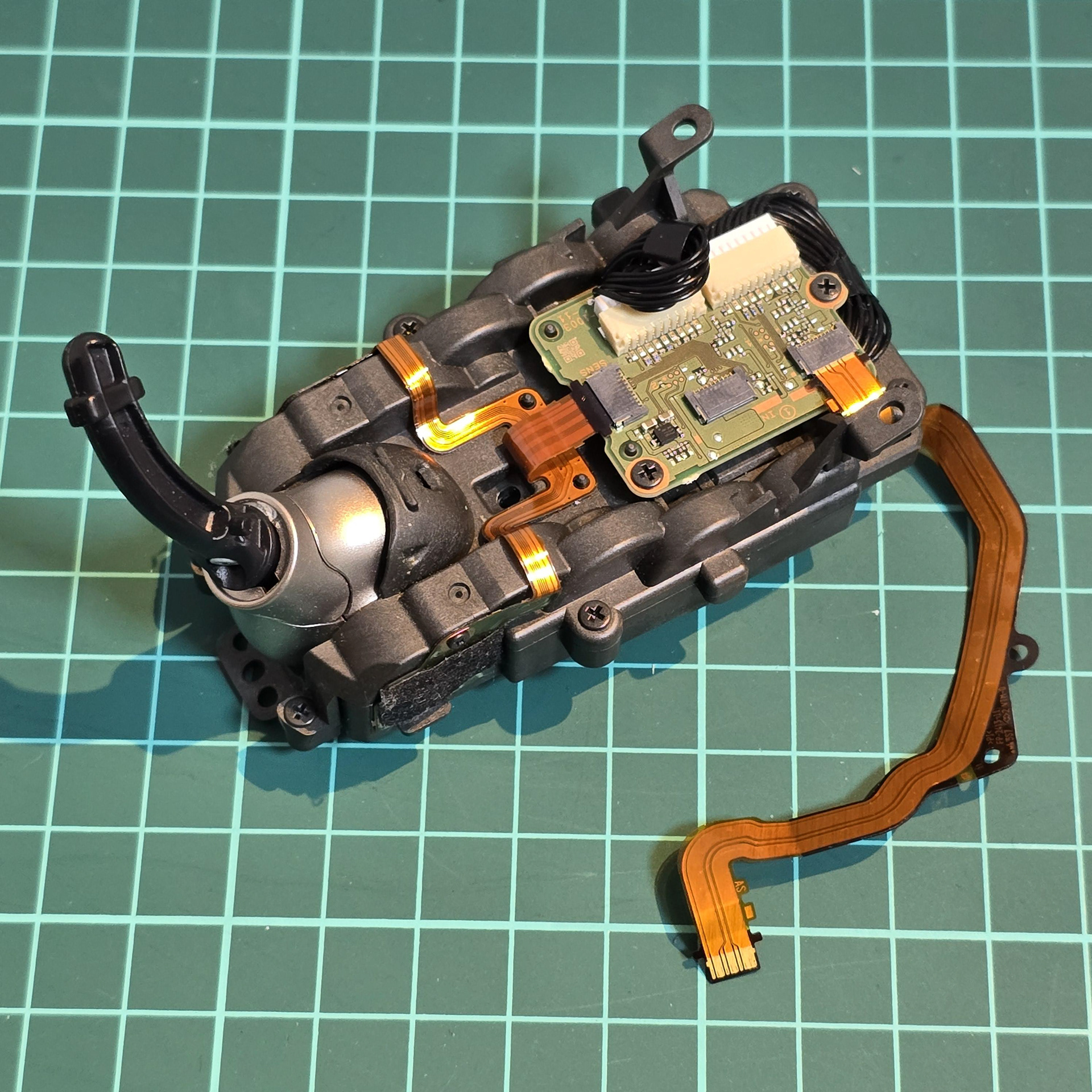
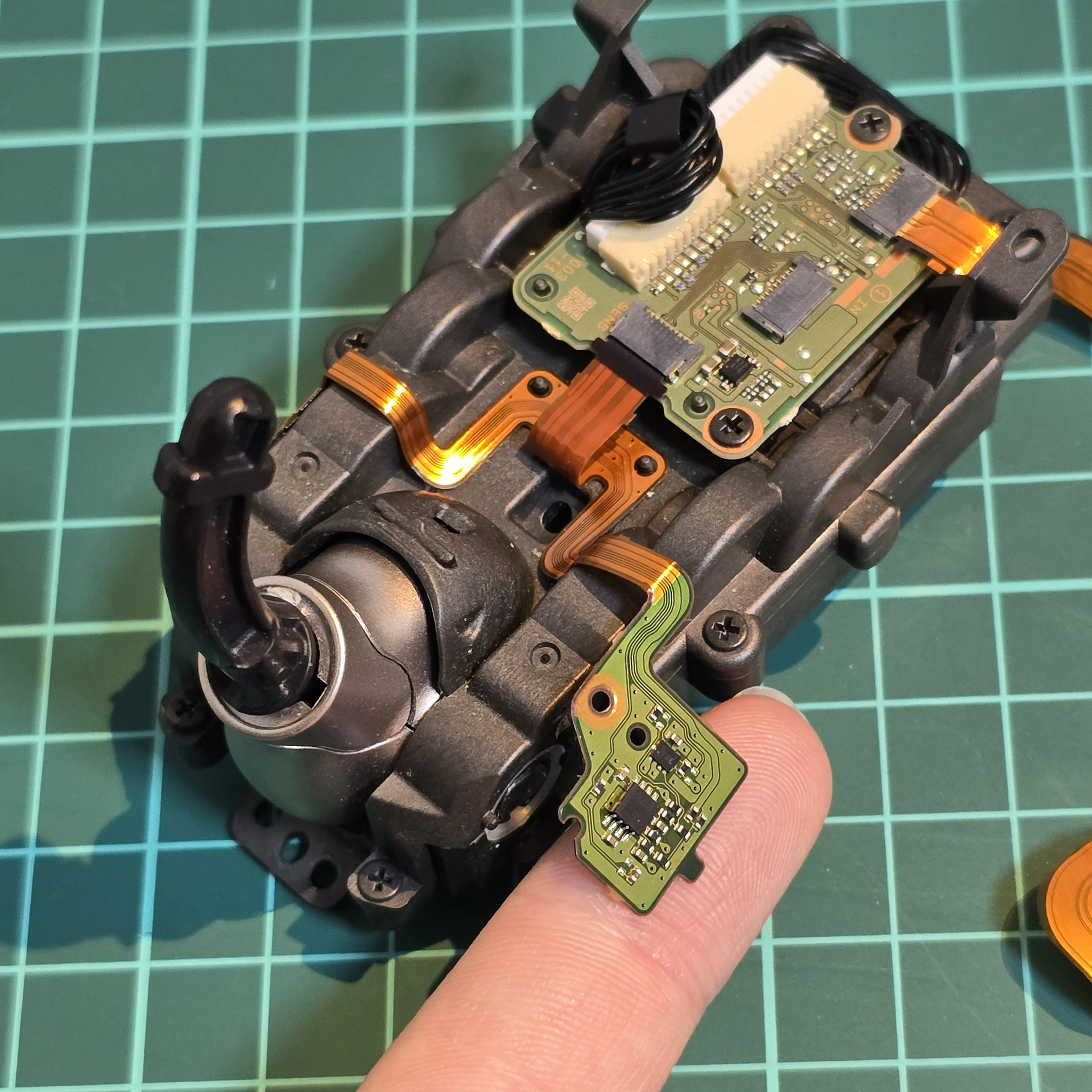
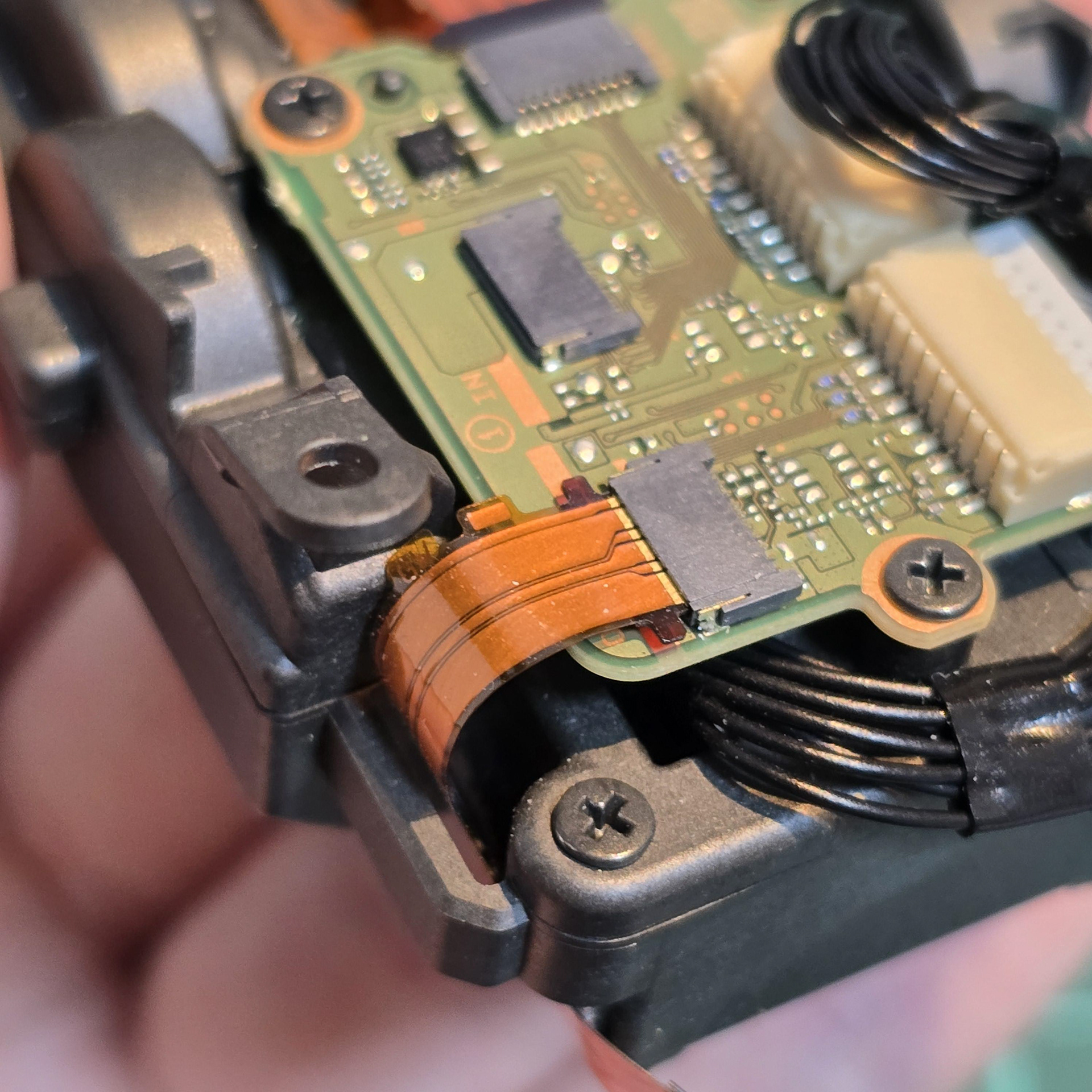
Remove the central screw holding the entire module in place and disconnect this flexible cable on the tail module board.
モジュール全体を固定している中央のネジを外し、テール モジュール ボード上のこのフレキシブル ケーブルを外します。

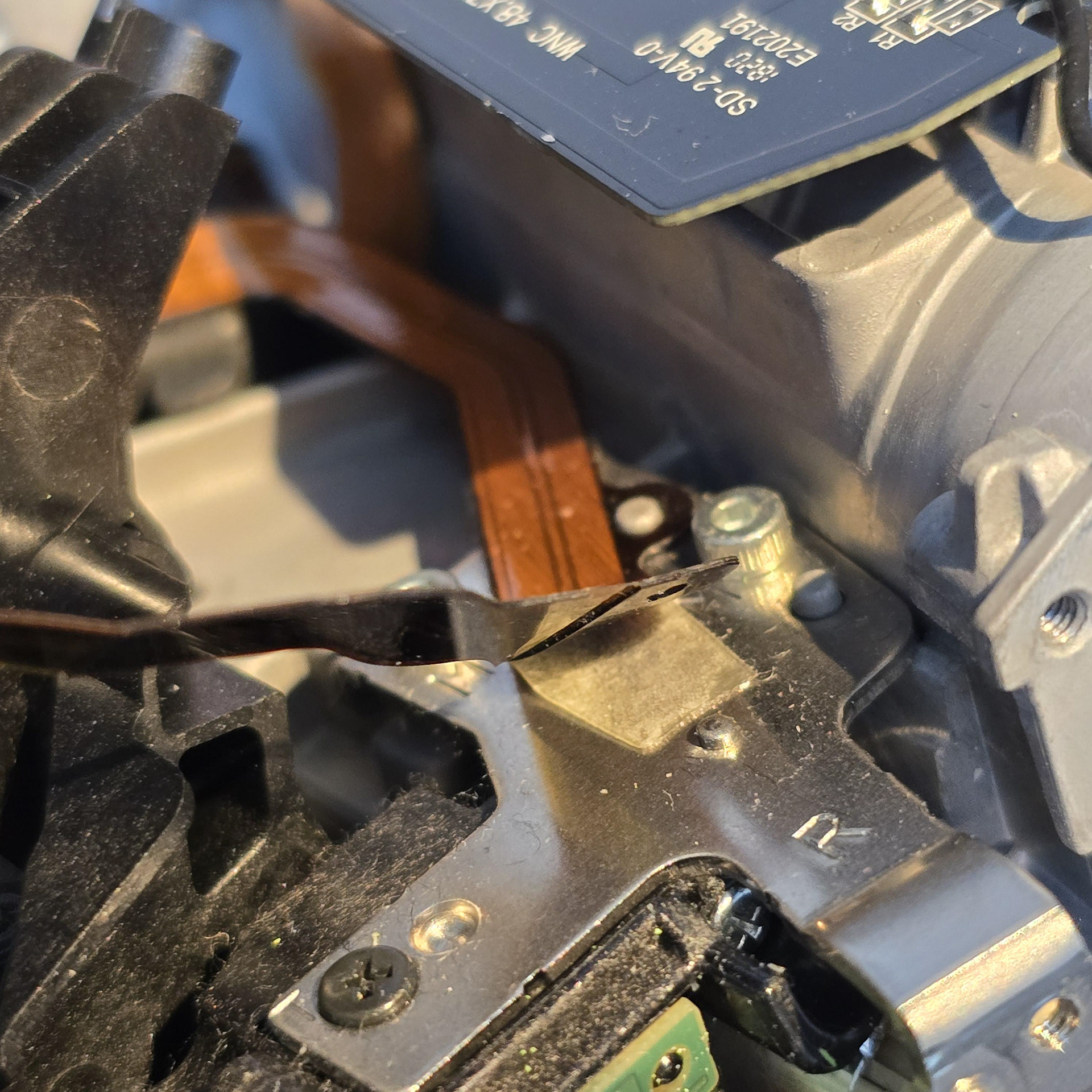
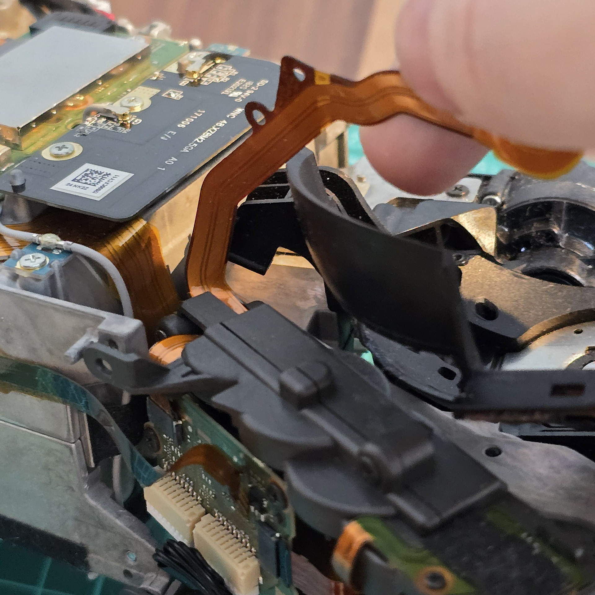
Flip the aibo over and look at the flexi leading from the tail module into the hip rotator. Disconnect it. The flexible cable is attached to a metal plate on the side and the cable is also slotted onto a metal peg. Slowly peel it free near this peg.
aiboを裏返し、尻尾モジュールから股関節回転部へと伸びるフレキシケーブルを確認します。これを外します。フレキシケーブルは側面の金属板に固定されており、さらに金属のペグにも差し込まれています。このペグの近くでゆっくりと剥がしてください。
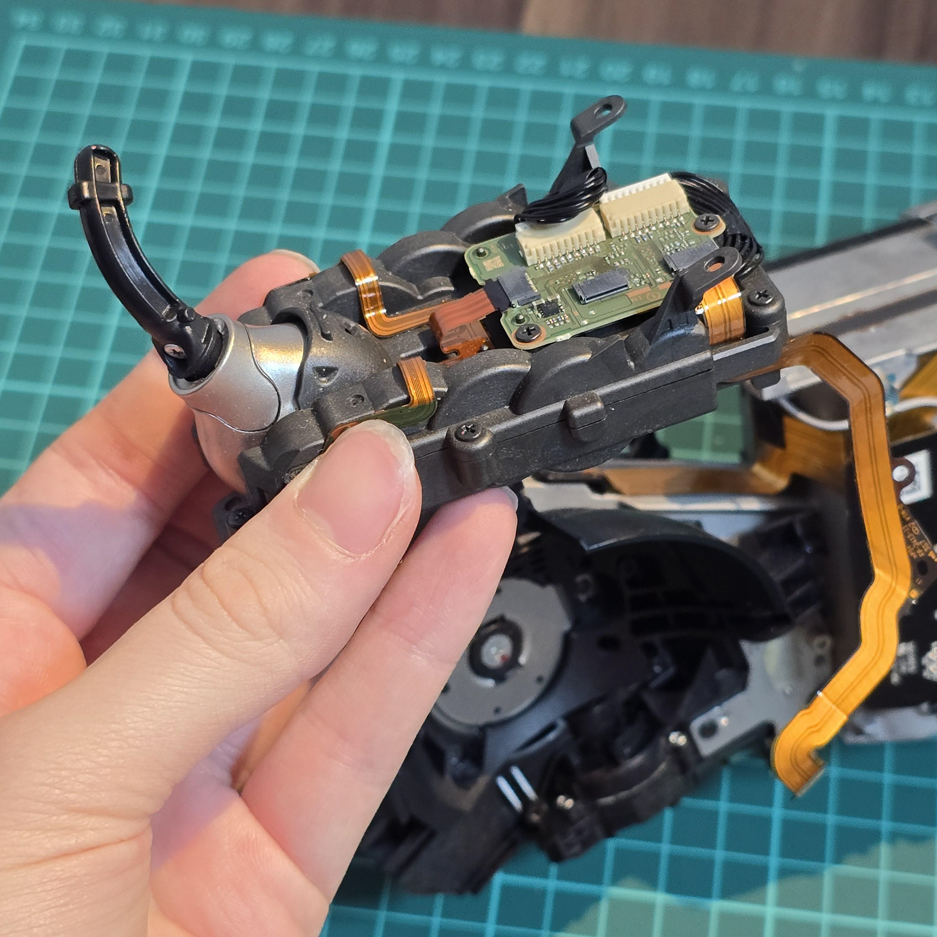
Once the adhesive has been peeled away from the flexible cable, the module is free to be lifted off of the aibo body.
フレキシブル ケーブルから接着剤を剥がすと、モジュールを aibo 本体から自由に取り外すことができます。
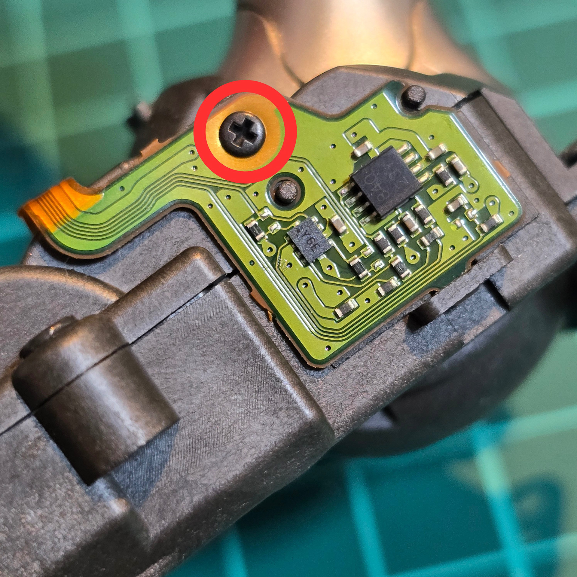
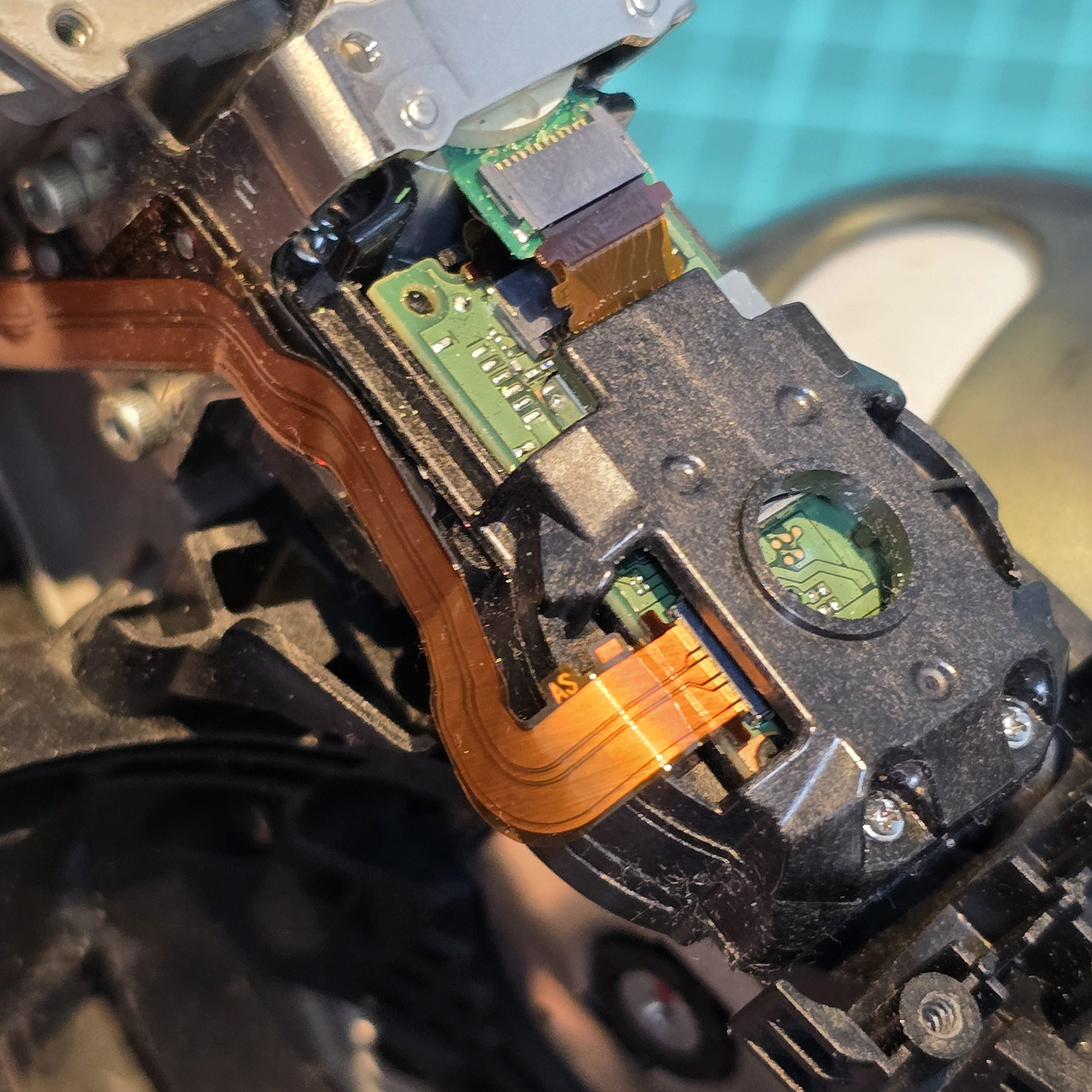
Next we are going to open the tail module. Turn your attention to the green flexible boards both sides of the module near the tail hub. Later production aibos have tape over this board - make sure to peel the tape back before continuing. Then take out the small screw to free the boards both sides. They have a little nib that hooks into a plastic loop, so carefully free them.
次に、テールモジュールを開けます。テールハブ付近のモジュール両側にある緑色のフレキシブル基板に注目してください。後期型のaiboではこの基板にテープが貼られています。作業を進める前に必ずテープを剥がしてください。次に、小さなネジを外して両側の基板を外します。基板にはプラスチックのループに引っ掛ける小さな突起があるので、慎重に外してください。
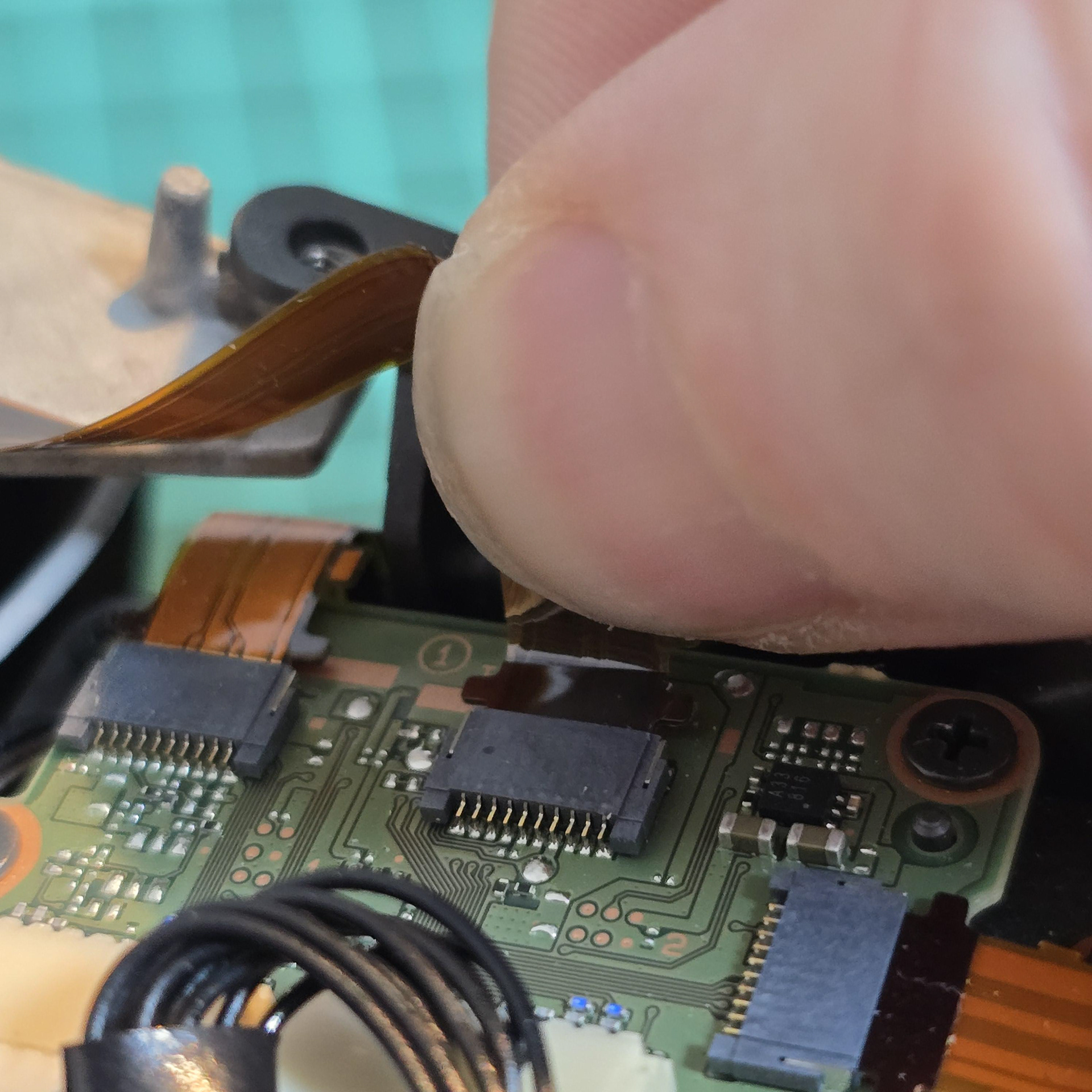
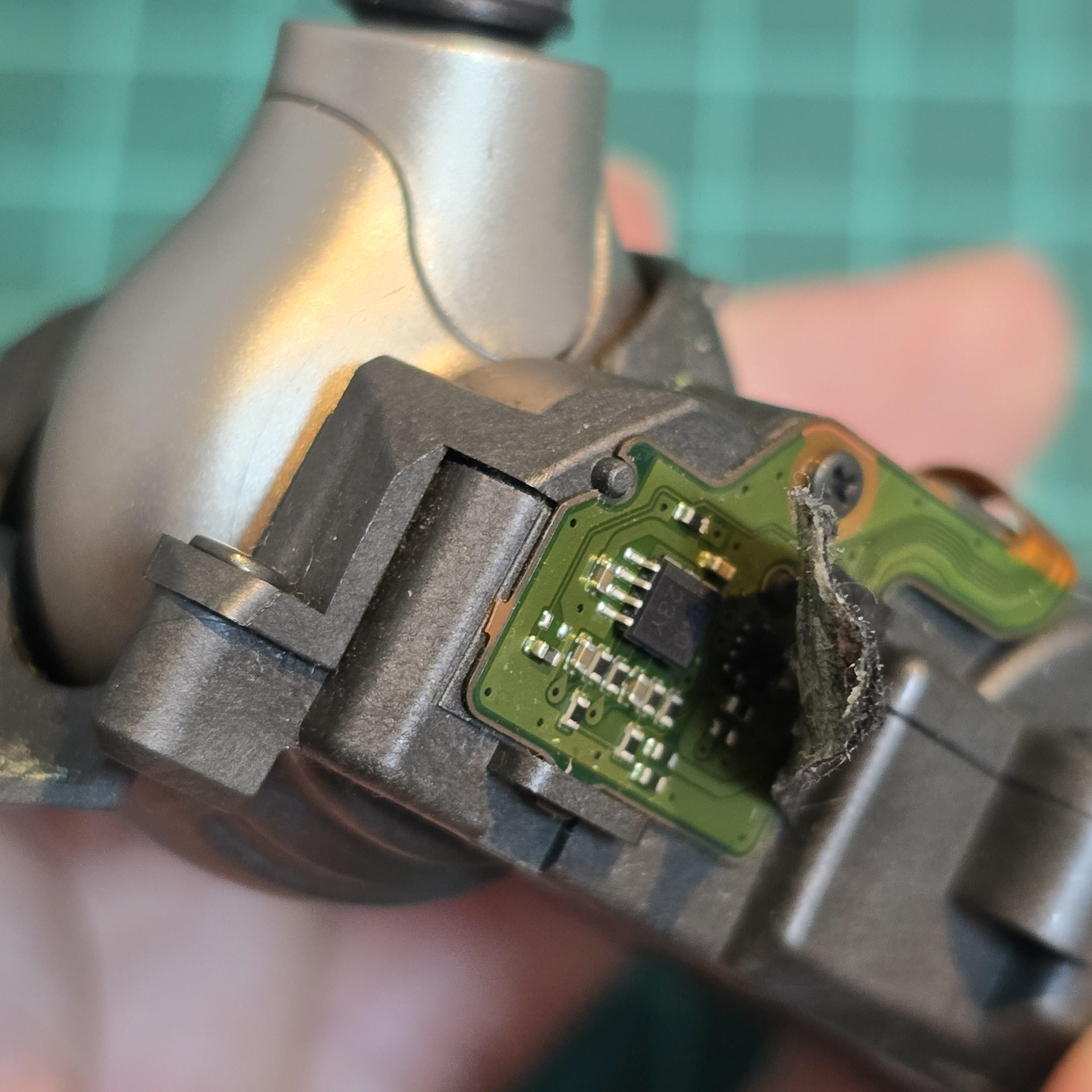
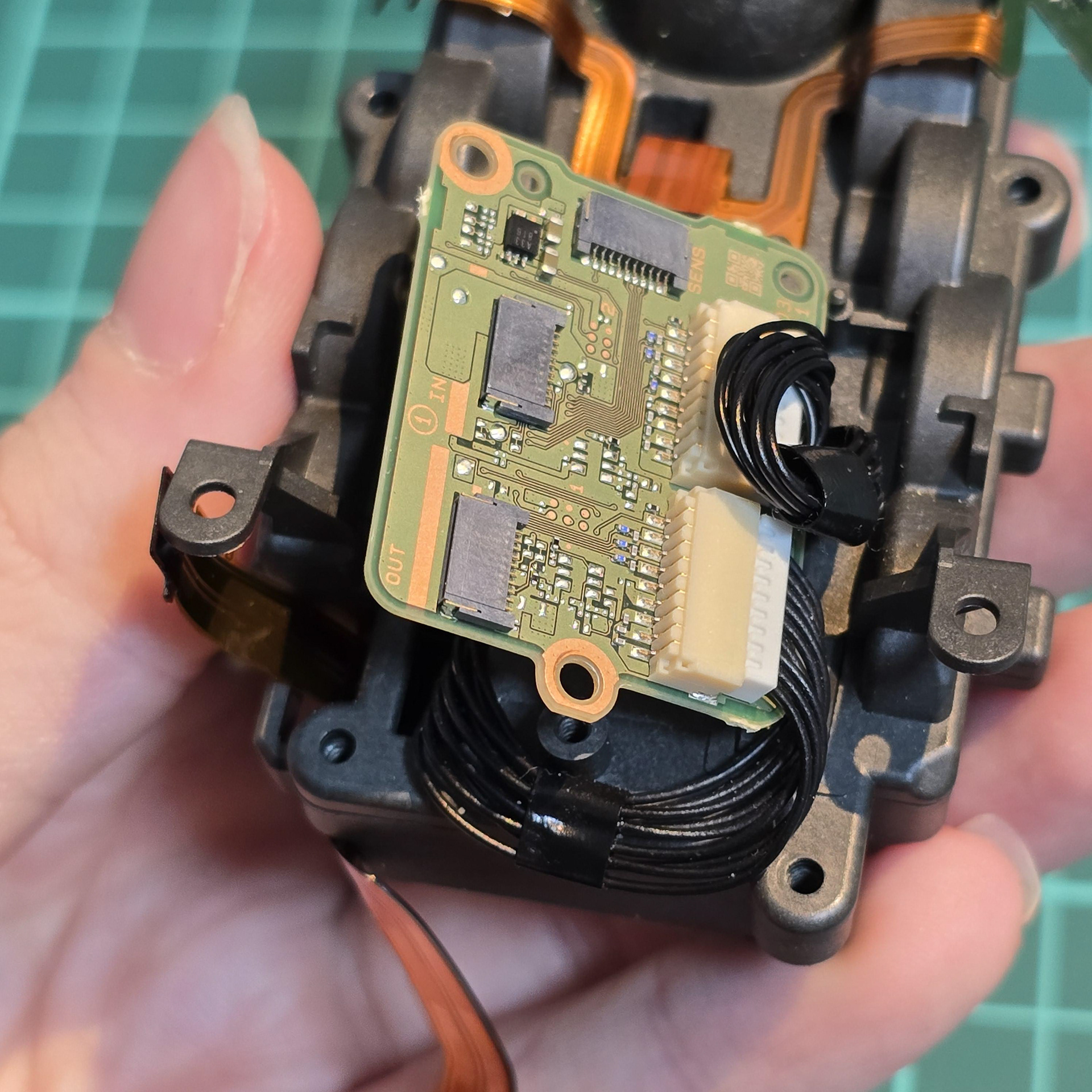
Then disconnect the flexible cable that is located next to the cable we disconnected before.
次に、先ほど取り外したケーブルの隣にあるフレキシブル ケーブルを取り外します。
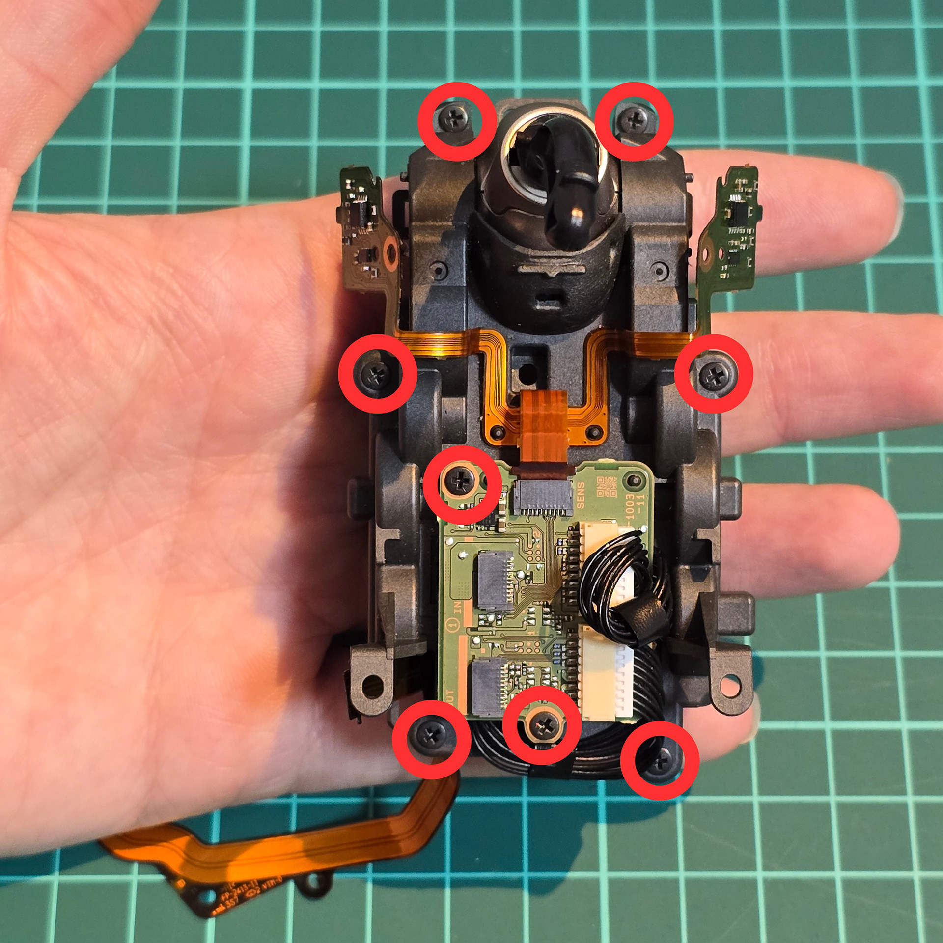
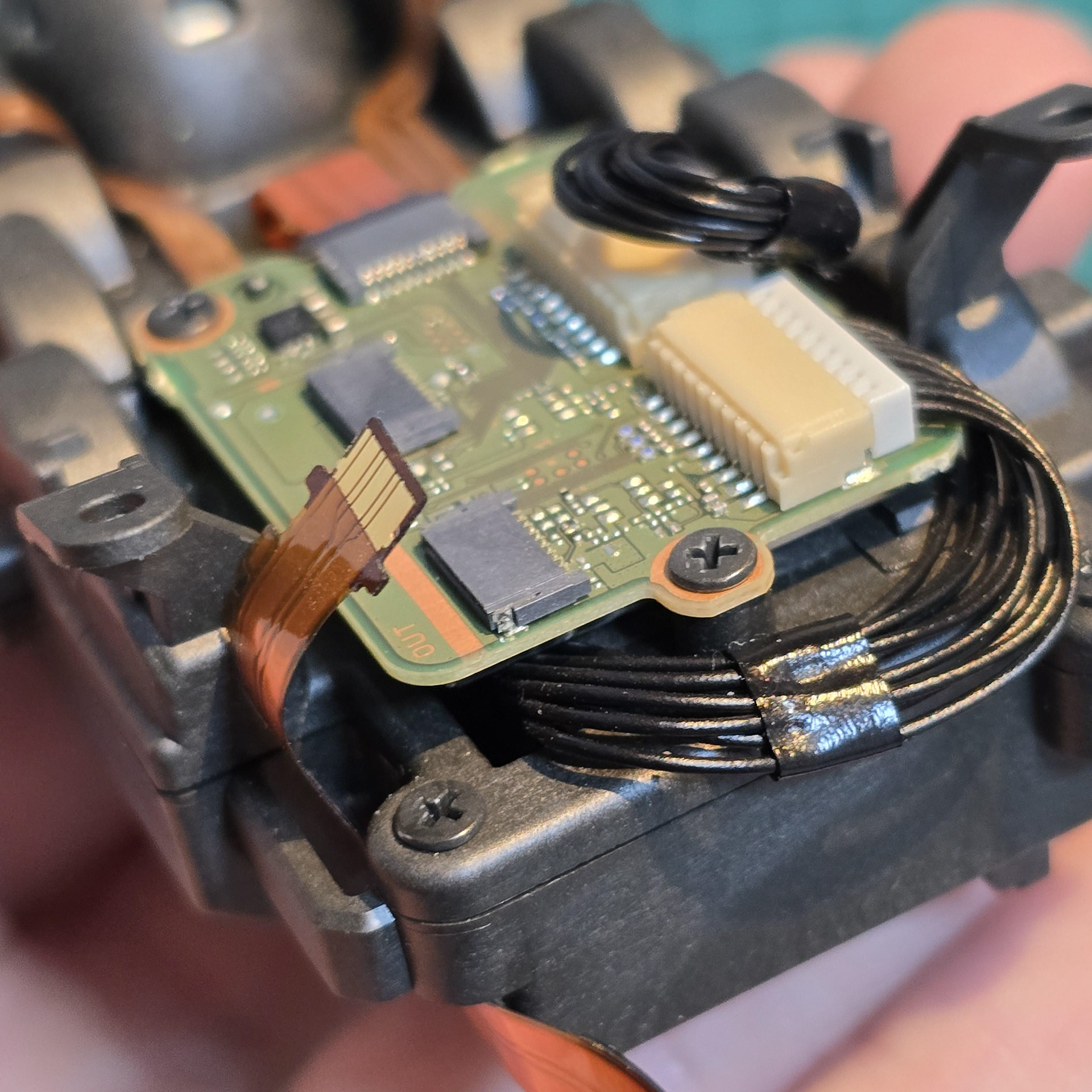
We are opening the entire module up, so go ahead and take out all of the screws I have circled in the diagram. This will free the circuit board on top as well as free the two plastic halves of the tail module casing. Lift up the board and disconnect the two black cables.
モジュール全体を開けるので、図で丸で囲んだネジをすべて外してください。これで上部の回路基板と、テールモジュールケースの2つのプラスチック製パーツが外れます。基板を持ち上げて、2本の黒いケーブルを外します。
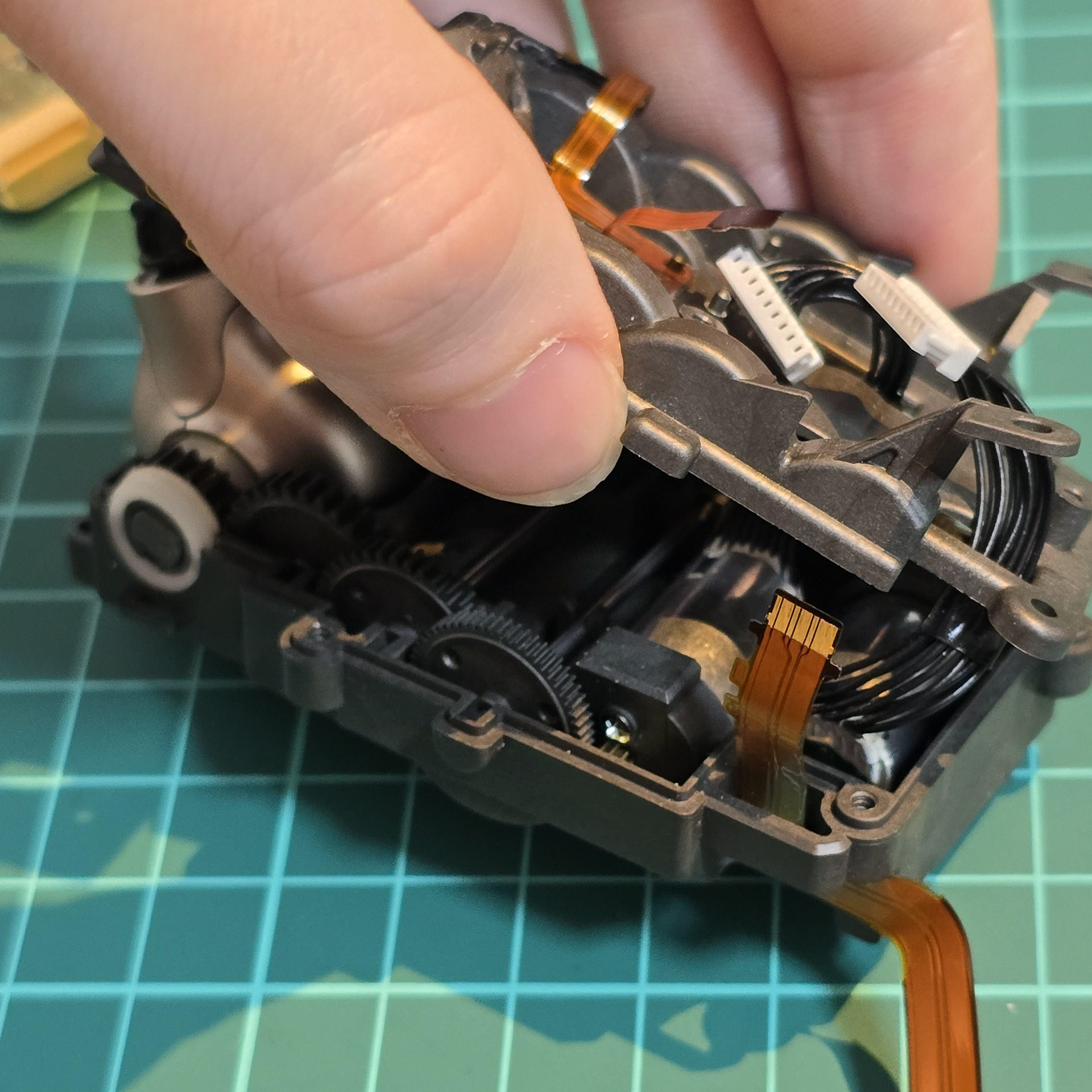
Once all of the screws and top board is removed, feed the black wires through their holes in the top plastic lid to fully separate the two halves of the tail module casing. Now you can access the servos and gearbox!
すべてのネジとトップボードを取り外したら、黒いワイヤーを上部のプラスチック蓋の穴に通して、テールモジュールケースの左右の半分を完全に分離します。これでサーボとギアボックスにアクセスできるようになります。
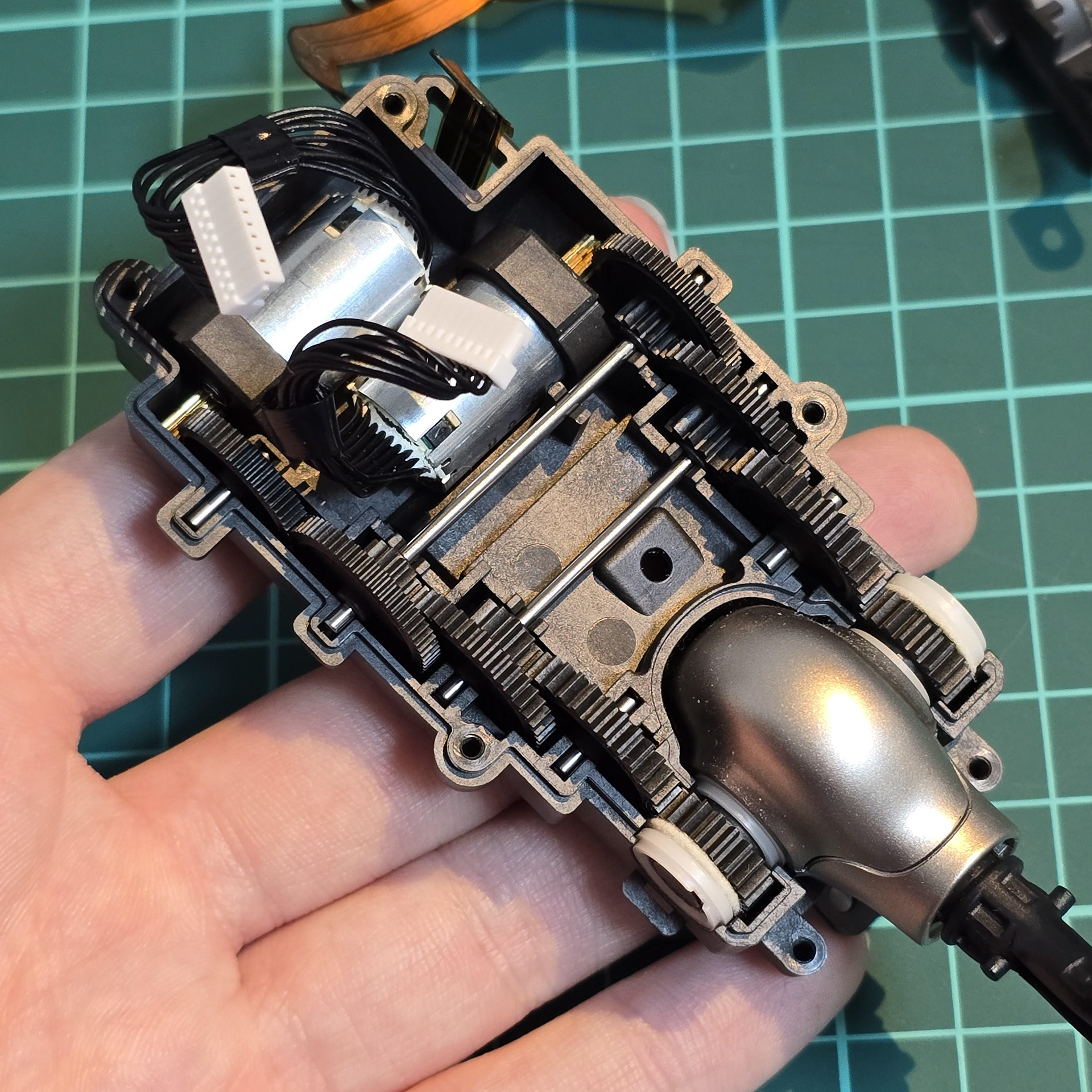
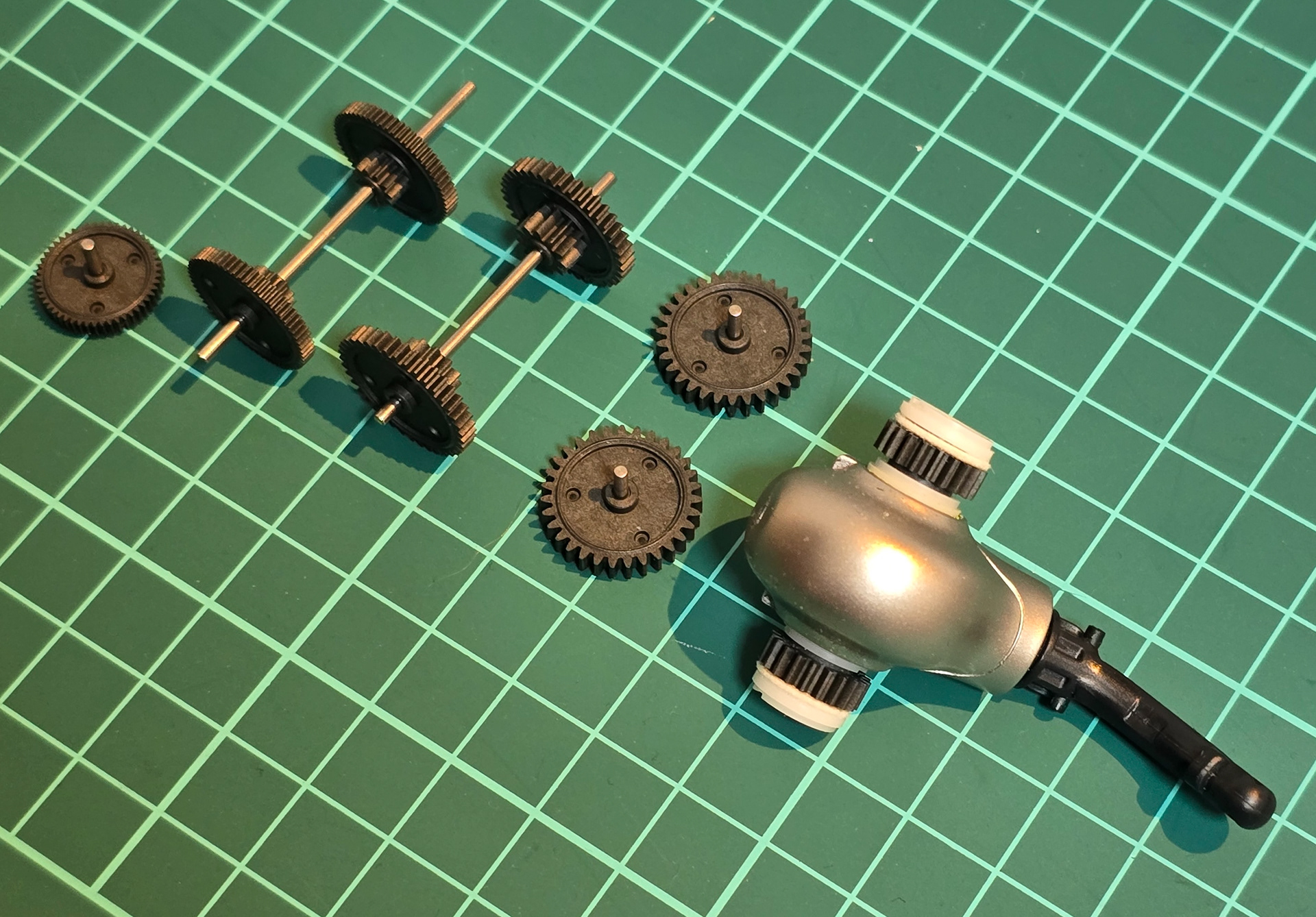
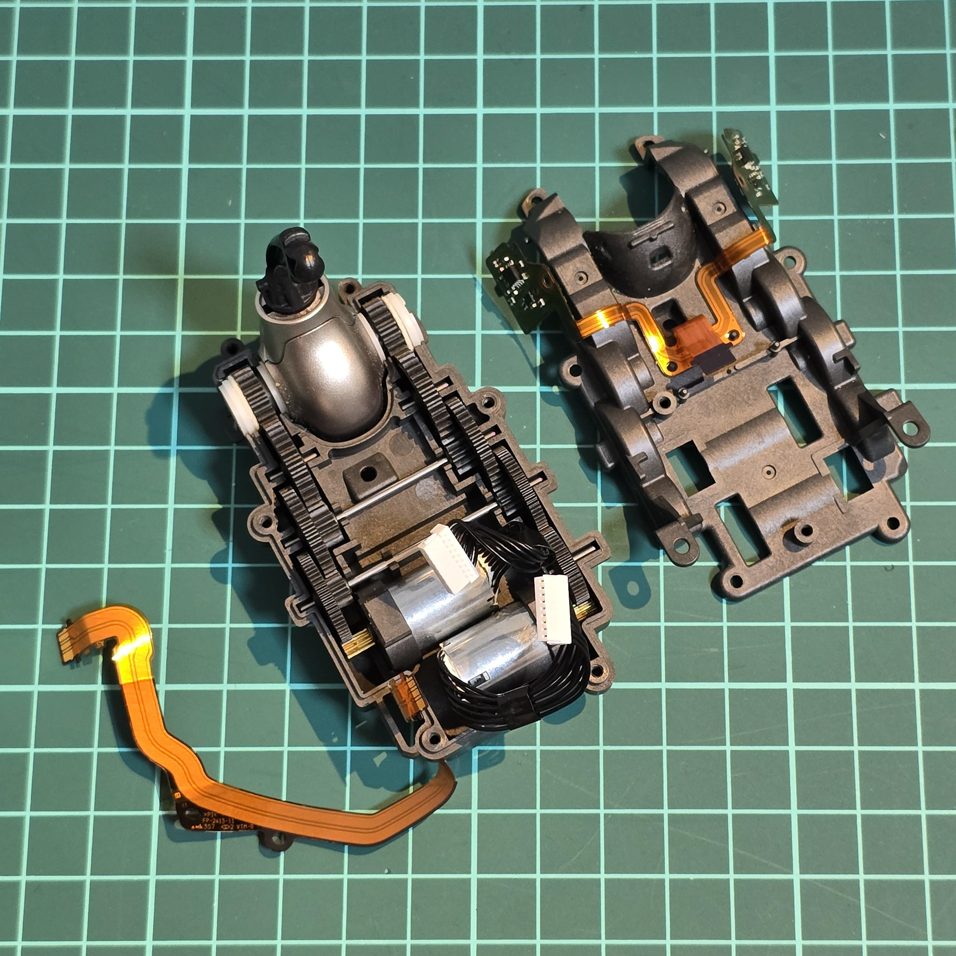
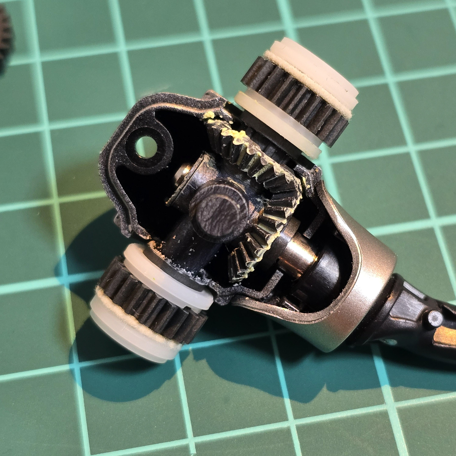
Top and exploded views of the tail gear array and servos.
テールギアアレイとサーボの上面図と分解図。
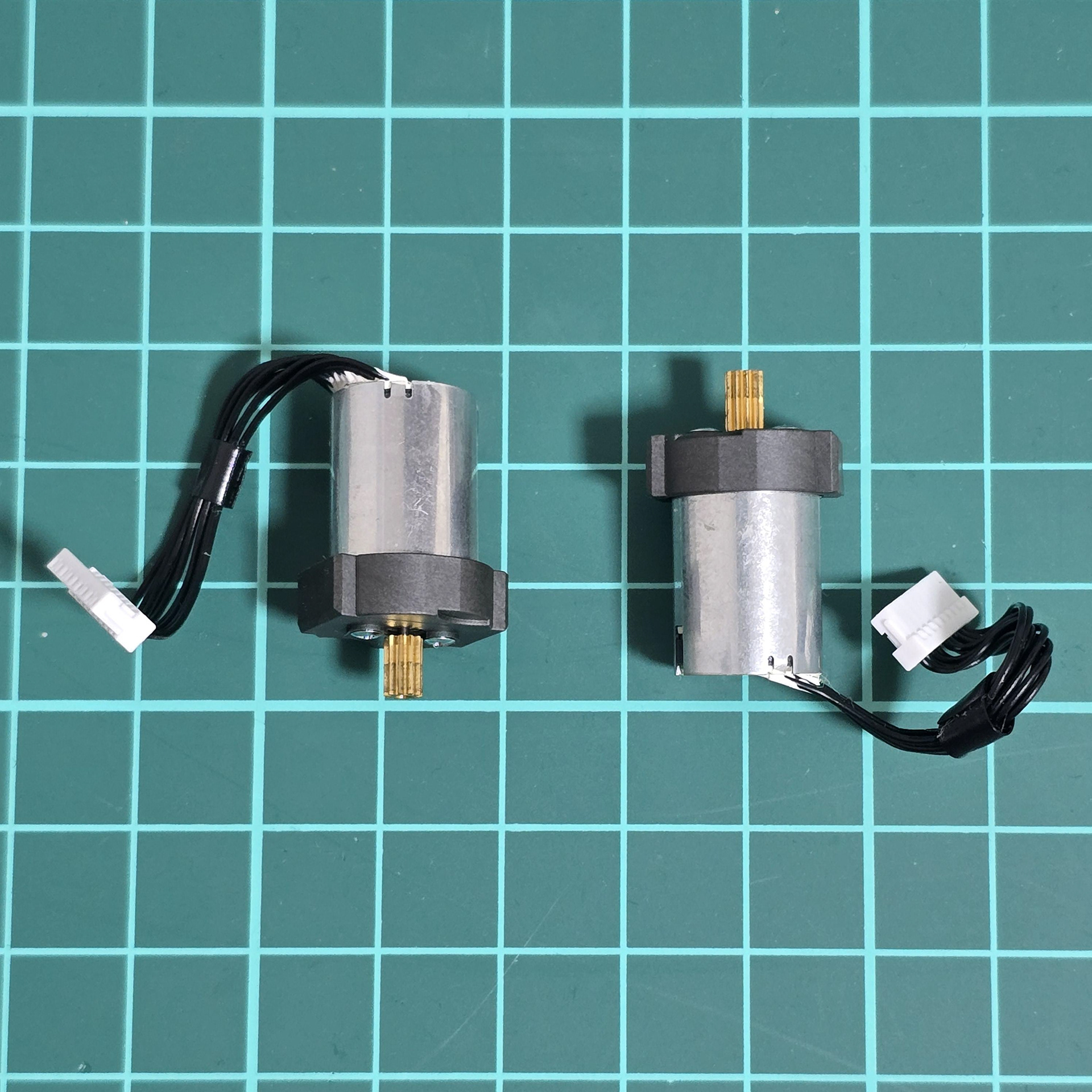
Above: The servos for the tail + Tail Hub.
上: テール + テール ハブのサーボ。
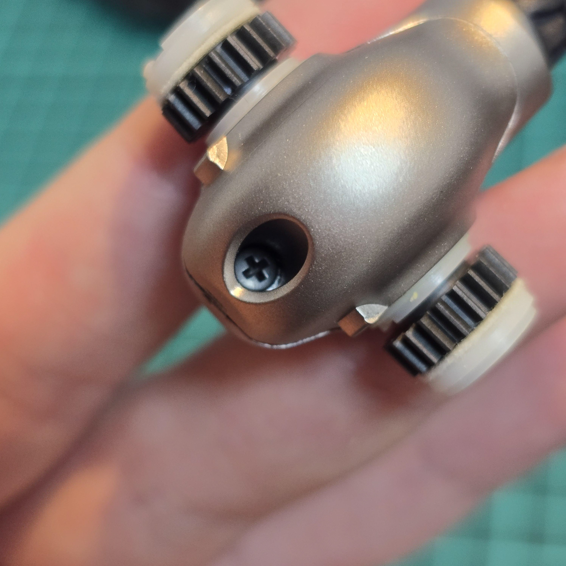
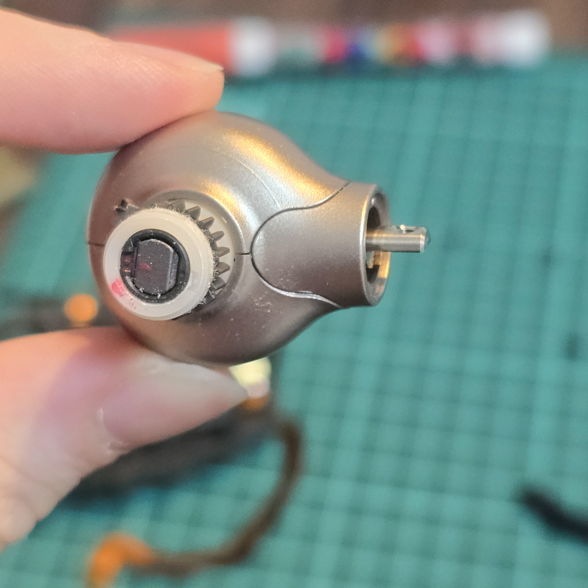
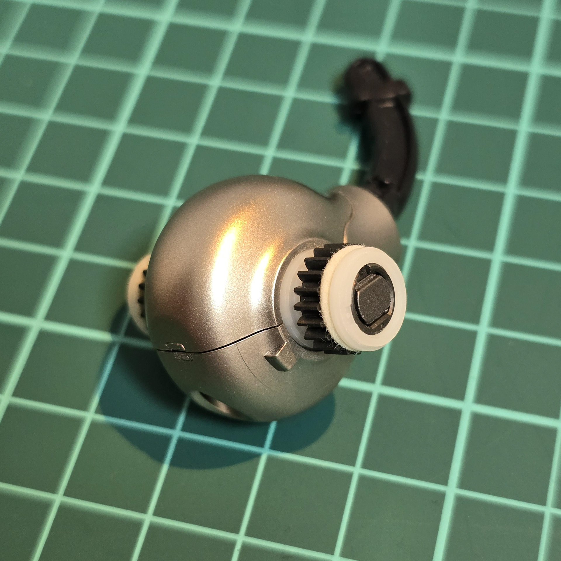
The tail hub can be opened by taking out the single screw and taking off the black tail nub. Once that is done, it can be opened. The top and bottom pieces lift off, while the side piece pulls up off the tail rod. When disassembling this piece, mark the side pieces and photograph them so you can put them back together exactly the same way to avoid positioning issues.
テールハブは、1本のネジを外し、黒いテールナブを外すと開けられます。これで開けられます。上部と下部のパーツは持ち上げて外し、側面のパーツはテールロッドから引き上げて外します。このパーツを分解する際は、側面のパーツに印を付けて写真を撮っておくと、位置合わせの手間を省くことができ、同じ手順で組み立て直す際に役立ちます。
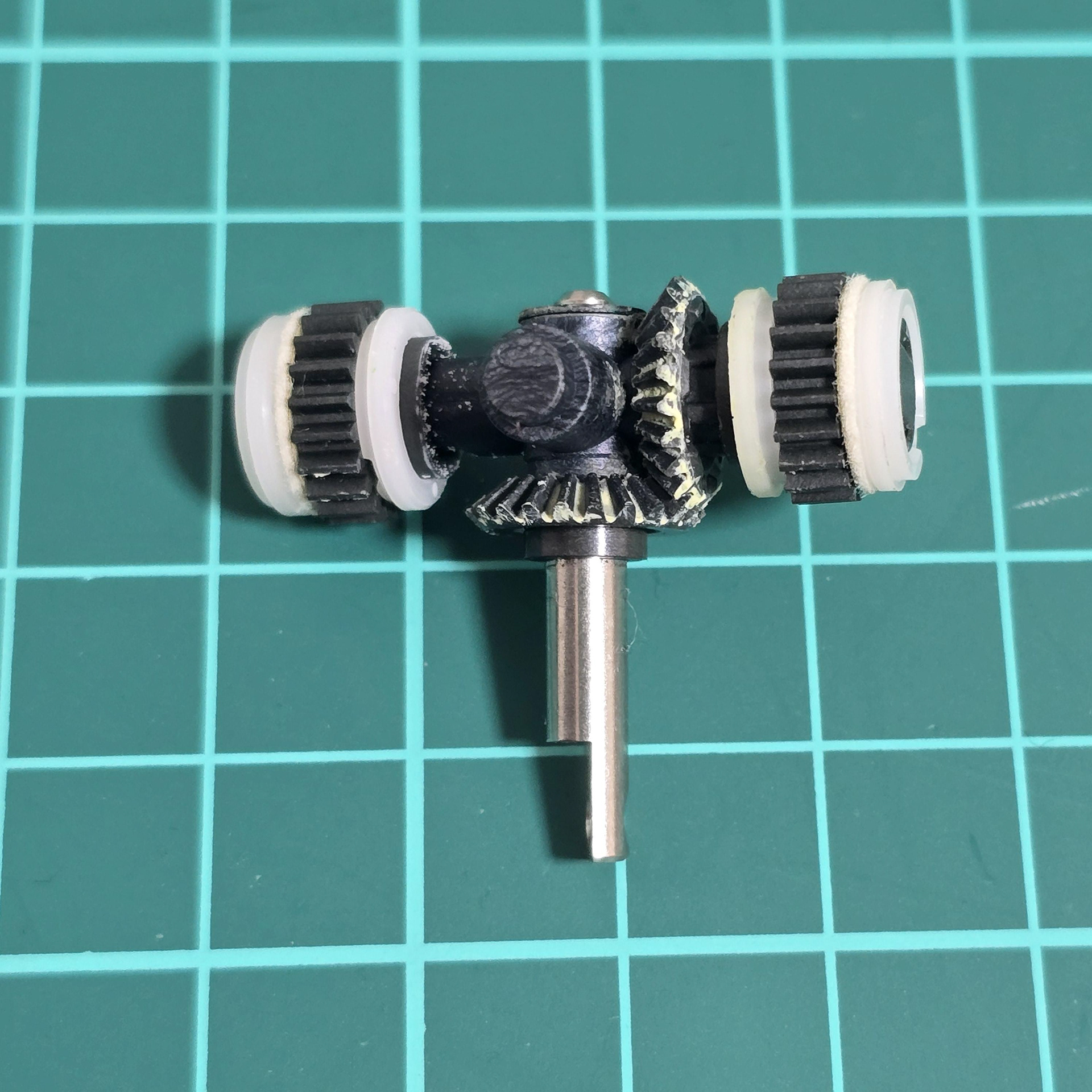
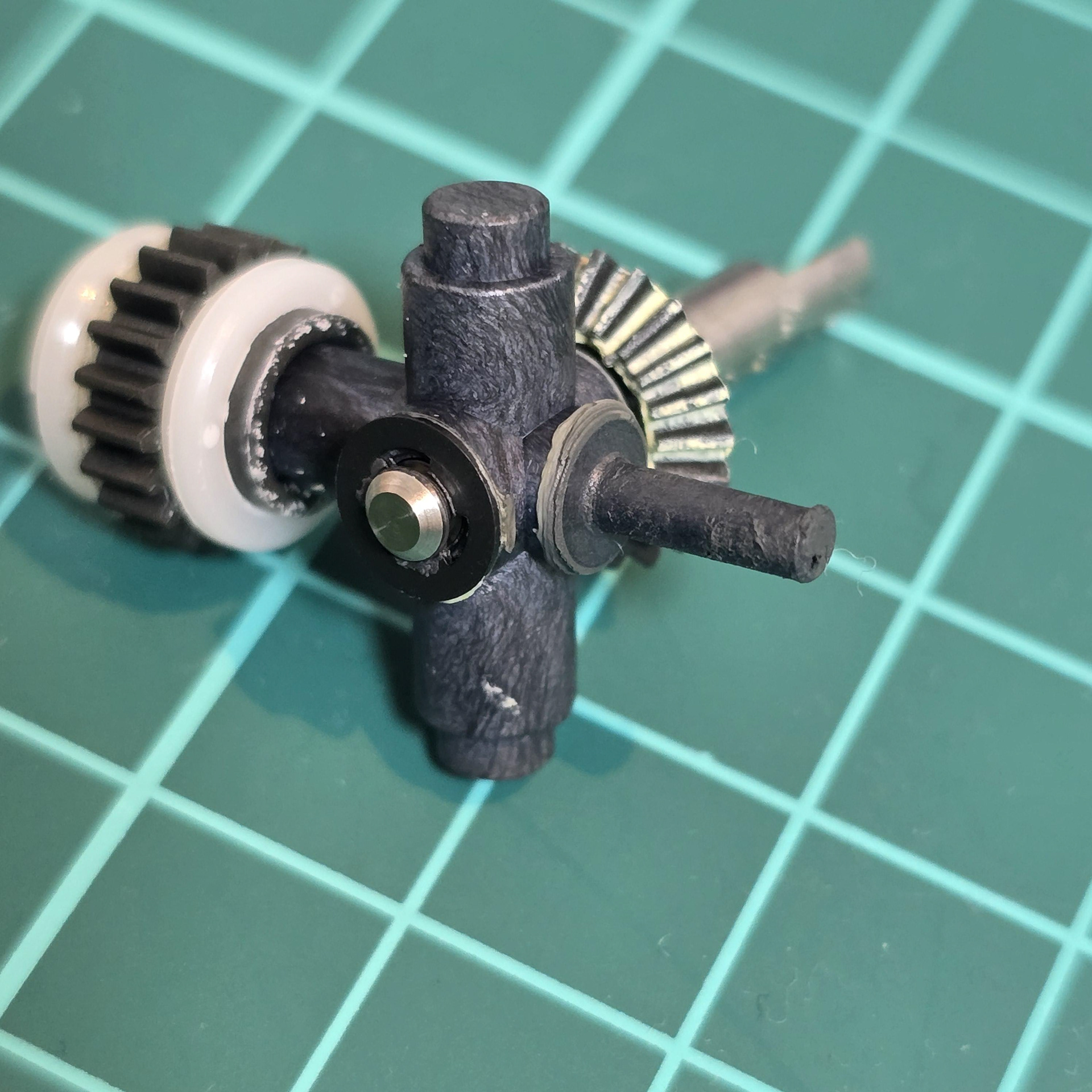
Above: Planetary gears and shafts.
上: 遊星歯車とシャフト。